Electricity - Revision Notes
CBSE Class 10 Science
In the recent times,life would be impossible without electricity. From lighting our homes, charging our devices, electricity has become an integral part of our day-to-day live. So it becomes necessary to understand the origin,characteristics and utilisation of electricity. In the current chapter we will discuss :
- Electric Current and Circuit
- Electric Potential and Potential Difference
- Circuit Diagram
- OHM's Law
- Factors on which the resistance of a conductor depends
- Resistance of a system of resistors
- Heating effect of electric current
- Electric Power
Charge (q)
Charge is a characteristic unit of matter by means of which matter experiences electric forces. It can be either negative (electron) or positive (proton)
“Coulomb” is the SI unit of charge, represented by C.
Net charge (Q) – Total charge
1C Net charge is equivalent to the charge contained in nearly electrons electrons.
Q = ne
(n is no. of electrons)
If Q= 1C, (negative charge on electron)
=
electron
Current (I)
Rate of flow of net charge is called current. Denoted by (I)
Electric current can also be defined as the amount of charge flowing through a unit cross-section in per second.
SI unit of current is “Ampere” .Denoted by A.
Ampere Defined as one coulomb of charge flowing per second.
In an electric circuit the electric current flow in an opposite direction to the flow of electron (–ve charge).This current is called conventional current.It flows from the +ve terminal battery or cell to –ve terminal. Small quantity of current are expressed in
mA (milli Ampere) =
µA (micro Ampere) =
Ammeter : It is an instrument used to measure the electric current in a circuit. It is always connected in series in a circuit. It has low resistance(practically).Ideally ammeter's resistance must be zero. It is represented as
Electric Circuit : It is a closed path along which the electric current flows.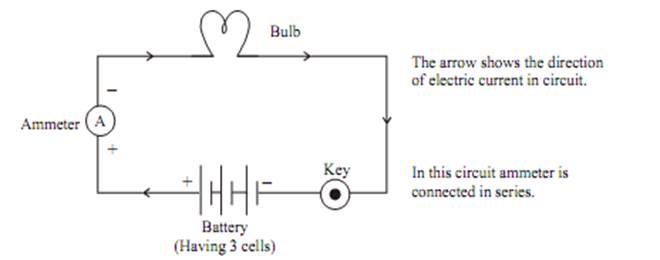
The electrons can only flow when there is difference of electric potential. For example “water flowing through a tube”. It is only possible when there is high pressure at one side and low at another side, then it will move from high pressure to low pressure.
In case of electric current, the flow of charge is made possible due to chemical action with in a cell that generates the potential difference across theterminals of the cell.
Electric potential Difference : It is defined as the work done in carrying a unit charge from one point to another in an electric circuit.
V – Potential Difference
W – Work
Q – Net Charge
SIunit of potential difference – Volts.Denoted by “V”. It is named after Alessandro Volta.
One Volt When 1 Joule of work is done in carrying one coulomb (1C)of charge from one point to another of a current carrying conductor then the potential difference is said to be IV.
Voltmeter It is an instrument, used to measure the potential differenceand represented by the symbol in an electric circuit. It isalways connected in parallel across the points between which the potentialdifference is to be measured. It has high resistance.
Circuit Diagram :A circuit diagram (electrical diagram, elementary diagram, electronic schematic) is a graphical representation of an electric circuit.
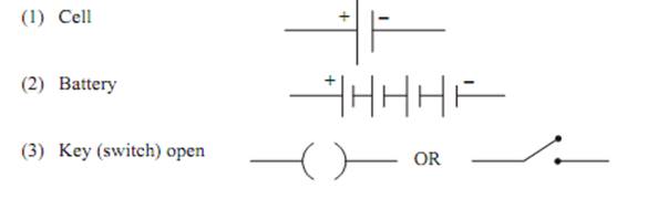
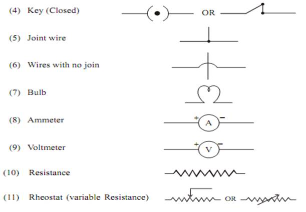
Symbols for some commonly used instrument in circuit diagram:
OHM's LAW
George Simon Ohm found the relationship between the current (I) flowing through a conductorand potential difference (V) across the terminals of a conductor using the circuit diagram. He observed that the potential difference and current varied linearly.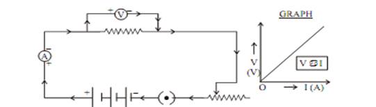
Ohm’s Law He stated that the electric current flowing through a conductor is directly proportional to the potential difference across its ends, under standard temperature and pressur conditions.
Where “R” is the proportionality constant for the given metal at given temperature and is called resistance.The graph between V and I is always straight line with slope equal to R.
Resistance : It is the property of a conductor that opposes the flow ofcurrent. It is represented by ‘R’ and symbol is
SI unit of resistance is “Ohm”.
1 Ohm : The resistance of a conductor is said to be one Ohm, when the potential difference across the conductor is 1V and the current flowing through it is 1A.
V = IR
IR = V
Rheostat
As we know that
So to increase or decrease the current accordingly in the circuit a component used is called “Rheostat”, that regulates the current without changing potential difference. Represented by “Rh”.
Its symbol is 
If a conductor has less Resistance, then more current will flow through it.
Factors on Which Resistance of a Conductor Depends
1. On its length (L)
2. On its cross sectional area (A)
3. On the nature of material.
(Resistance) R L (Directectly prop. to length)
(inversely prop to cross-sectional area)
Where “ ” (rho) is a proportionality constant known as resistivity of the material of conductor.
Resistivity ( ) : The resistance offered by a wire of unit length and unit cross-sectional area is called resistivity.
Its SI unit is
For a material irrespective of length and area, the resistivity is a constant.
Resistivity of a Material varies with Temperature
Resistivity is the measure of resistance of a material. In other words, upto what extent will the material resist current flow.
Resistivity of an alloy (homogeneous mixture of metals) is generallyhigher than of its constituent metals. Example: Constantan (alloy of Cu & Ni)
Alloys have high resistivity and do not oxidise (burn) readly at hightemperature, for this reason they are commonly used in electrical heating devices,like electric iron, heater, toasters etc. For example “Tungsten” as filament of electric bulb.
- Resistance of a system of resistors
Resistance in Series (Maximum Effective Resistance)
Let us take three conductors/resistors of resistance R1, R2 and R3 that areconnected in series in a circuit.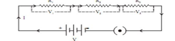
Ohm’s law stated
V = IR
The current (I) flowing through the resistance in series will remain same,where as the potential difference (V) across each resistor will be different.
V = IR
Total potential difference
Thus, we conclude that effective Resistance of the several resistors joinedin series is equal to the algebraic sum of their individual resistances.Also, the net resistance increases when resistors are connected in series.
Resistance in Parallel (Minimum Effective Resistance)
Let us take three resistors of resistance that are connectedin parallel in the electric circuit.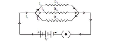
Now,
Total current substitute the value of
Thus, we conclude that the reciprocal of total effective resistance of theseveral resistors connected in parallel is equal to the sum of the reciprocals of the individual resistances.Also ,the net resistance reduces when resistors are connected in parallel.
Disadvantage of Series Connection in an Electric Circuit
1. In series connection if any of the component fail to work, the circuit will break and then none of the component (ex. TV, bulb, fan..) willwork.
2. It is not possible to connect a bulb and a heater in series, because they need different value of current to operate properly.
Hence, to overcome this problem we generally use parallel circuit.
Heating Effect of Electric Current
Explanation Battery or a cell is a source of electrical energy.
1. Battery or cell (Chemical reaction in it will produce potential difference at its two terminals)
2. Electron will come in motion to flow current through resistor
3. To maintain this current, the sources has to keep expending its energy.
4. Part of this energy is consumed in useful work(Like rotating of fan)
5. Rest of energy of source is converted into heat, that raises the temperature of gadget.
6. This is known as heating effect of electric current.
7. This effect is utilized in devices such as electric heater, iron etc.
Mathematical Expression
Let us suppose that current (I) is flowing through a resistor of resistance(R) for the time (t). The potential difference across the resistance is (V).
Work done in moving the charge Q will be
W = VQ
Then power, [Rate of change of work done]
=
Heat energy supplied by the source for time t will be
(H = P t)
Put equation (i) in equation (2)
H = VIt
= (IR) It
This is known as Joule’s Law
The law stated that the heat produced in a resistor is :
(i) directly proportional to square of the current (I)
(ii) directly proportional to resistance (R) for given current
(iii) directly proportional to time (t) for which current flow through resistor.
Application of Heating Effect of Electric Current
1. Used in electric iron, toaster, oven, heater etc.
2. It is also used in bulb to produce light.
(Filament of bulb is made of strong metal with high melting point suchas tungsten
(). This filament can retain as much of theheat generated as possible, to become very hot and emit light)
3. It is also used in the “fuse connected in an electric circuit. Fuse is asafety device, that protect the circuits and appliance by stopping theflow of high current. The wire of fuse is made of an alloy of metalse.g., Aluminium Copper, Iron, Lead etc. The alloy should be of lowmelting point and high resistivity, fuse is always connected in seriescircuit. When large current flows through the circuit, the temperatureof fuse wire will increase. This melts the fuse wire and breaks thecircuit.
“ Fuses” used for domestic purposes are rated as 1A, 2A, 3A, 5A, 10Aetc. for various operation depending upon the power of appliance using.
Example : let us consider an appliance “electric Iron” which consume1KW electric power, at 220V
P = VI
I=4.54A
In this case a 5A fuse is required.
Electric Power : In case of electricity, it is defined as the rate of changeof electrical energy dissipated or consumed in an electric circuit.
P=VI
Or
Or
SI unit of electric power is “Watt” (W)
1 Watt Defined as the power consumed by a device, when IA of current passes through it at the potential difference of IV.
P=VI
1 Watt = 1 Volt 1 Ampere
Electrical Energy
SI unit of electrical energy =Ws or J
Commercial unit of electrical energy=KWh or one unit
= 1000Wx3600s
= 36 x 10Ws
= 3.6 x 10J (SI unit Ws=J)
One horse power = 746W
What you have learnt
- A stream of electrons moving through a conductor constitutes an electric current.
Conventionally, the direction of current is taken opposite to the direction of flow ofelectrons.
- The SI unit of electric current is ampere.
- To set the electrons in motion in an electric circuit, we use a cell or a battery. A cellgenerates a potential difference across its terminals. It is measured in volts (V).
- Resistance is a property that resists the flow of electrons in a conductor. It controlsthe magnitude of the current. The SI unit of resistance is ohm (Ω).
- Ohm’s law: The potential difference across the ends of a resistor is directlyproportional to the current through it, provided its temperature remains the same.
- The resistance of a conductor depends directly on its length, inversely on its area ofcross-section, and also on the material of the conductor.
- The equivalent resistance of several resistors in series is equal to the sum oftheir individual resistances.
- A set of resistors connected in parallel has an equivalent resistance given by
- The electrical energy dissipated in a resistor is given byW = V × I × t
- The unit of power is watt (W). One watt of power is consumed when 1 A of currentflows at a potential difference of 1 V.
- The commercial unit of electrical energy is kilowatt hour (kWh). 1 kW h = 3,600,000 J = 3.6 × 10 J.