Programming (OLD) - Adv. Prog. Dev. Methodology
CBSE Class 12 Informatics Practices
Revision Notes
Chapter -2
Advanced Programming Development Methodology
1. What is a system?
A System is a collection of elements or components that are organized for a common purpose.
System Software : System software is a type of computer program that is designed to run a computer’s hardware and application software. The operating system (OS) is the best-known example of system software. The OS manages all the other programs in a computer.
2. Steps in SDLC(Software Development Life Cycle): SDLC is a process that consists of a series of planned activities to develop or alter the Software Products. Software Development Life Cycle (SDLC) is a process used by the software industry to design, develop and test high quality softwares.
a) Planning and Requirement Analysis
b) Feasibility study
c) Designing the Product Architecture
d) System analysis
e) System design
f) Coding
g) Testing
h) Implementation and maintenance
Block Diagram for SDL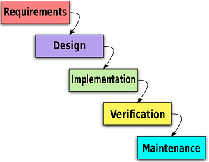
3. Tools used for system analysis
a) Data flow diagram DFD
b) Process chart
c) Data dictionary
d) Decision table
e) Decision tree
System: A system is a collection of interrelated different component which work together. For eg. A computer system is a collection of H/W and S/W.
1. Prilimnary Study/Survey This is a very first step for developing a system.During this phase the main effort is given on the problem with the existing system.here the key question is “why do we need to develop a new system”,”what is the problem with the existing system”.Here the system analyst do the requirement analysis.
2. Feasibility Study. In this phase we find out whether the new system is worth Developing or not, means the organization will be benefited by the new system or not. Does the organization has all the facilities, all the tools for developing a new system. After the feasibility study a feasibility report is prepared and if the report is positive new system is approved to be developed.
There are 3 types of feasibility study.
a) Economic F.S: In this F.S the analyst do the cost-benefit analysis that is how much cost would be required for the system to be developed and whether the benefit will outweigh the cost. If benefit is more than the expenditure or cost then it is approved.
b) Technical F.S: In this F.S technical requirements are looked for like whether the technical software or hardware needed to develop a s/w are easily available.
c) Behavioural F .S: In this F.S it is checked whether the people or the users will be comfortable with the new s/w as they need to be trained on the usage of the software.
After all three types of FS if all are positive the system analyst moves on to the next step.
3. Investigation and fact recording:
In this Phase information and facts or raw data is collected for the new system. For this analyst applies the following procedures:
a) Interviewing: Interview is taken individually from the employees.
b) Questionaires: set of Questions are given to everyone and answers are collected to know about the problem.
c) On site observation: By really going on to the site and watching the actual working of the organization without letting the people to know that they have been watched.
d) Sampling: To collect or calculate something on large data , some samples are collected randomly on weekly or monthly basis and then calculation is done.
e) Reviewing ofthe manuals. Last option is to view or by reading the documents and manuals of the organization.
4. System Analysis: In this phase complete analysis of the current system is done in order to reach at the specifications of proposed new system. following points are analyzed:-
a) Goals and objectives of the the proposed system.
b) Fundamental actions that must take place in the s/w
c) Outputs to be produced
c) Inputs to be used
d) Processes to be performed
e) Interfaces to be provided
f) Performance requirements to be met.
g) Organizational and other constraints to be met.
5. System design:This phase is concerned with the design of final system. Here the modules for the new system are designed and the relation between the modules. Following diagram shows the steps of designing.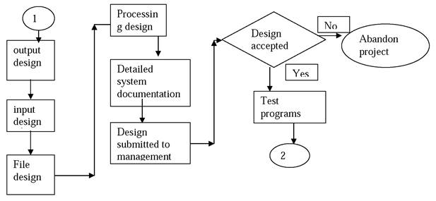
6. Coding: In this phase a particular language is taken and programming is done or coding is done for that new system.For ex c,c=+,java,.net etc
7. Testing. After coding testing is done. In testing it is checked whether the s/w is working according to the need and requirements of the user. Whether the s/w is running successfully without any error and is running for all types of data combinations.
Types of Testing:
a) Online Response: Online Response of the system is checked.
b) 5tress Testing. In this Testing System is checked under heavy workloads.
c) Volume Testing. In this large no of data transaction is teseted to ensure the proper functioning of hardware and software.
d) Recovery Testing. System is forced to have failure so that recovery can be tested.
e) Unit Testing. In this testing each or individual module is tested for errors and proper functioning.
f) Integration Testing. In this integration of modules is done and proper interface of the modules with each other is tested.
7. Implementation. After all this The new system is finally implemented means used by the Clients for whom the s/w has been developed. It is used by the end users. In this phase training to the users is provided on the newly made s/w.
8. Maintenance. The last step is maintenance. Maintaining and updations of the s/w from time to time is very nessesary as the needs of the user changes periodically So the new requirements need to be incorporates into the s/w.
Hardware maintenance is also necessary which aids in the proper functioning of s/w.
Maintenance is of 3 types
1) Corrective maintenance
2) Adaptive maintenance
3) Perfective maintenance
ENTITY RELATIONSHIP MODEL
ER model is a high level, conceptual model that describes data as entities, attributes, and relationships.An entity relationship model also called an entity-relationship (ER) diagram is a graphical representation of entities and their relationships to each other, typically used in computing in regard to the organization of databases or information systems.
ENTITY
A real world object is called entity. An entity can be a person, place, thing or any concept.
An entity is an object that exists and is distinguishable from other objects.
EXAMPLE:


ENTITY TYPE. An entity type is a set of same type, which share common properties.
EXAMPLE: CAR
ENTITY INSTANCE: Entity instance is example of an entity.
EXAMPLE: INDICA, SANTRO, ZEN, MARUTI
ATTRIBUTE: Properties or characteristics of an entity.
EXAMPLE: STUDENT (RNO, NAME, CLASS, MARKS)
NOTE: WHERE RNO, NAME, CLASS AND MARKS ARE ATTRIBUTES OF STUDENT ENTITY.
TYPES OF ATTRIBUTES
1. Key attribute
2. Simple single value attribute
3. Composite attribute
4. Single value attribute
5. Multivalued attribute
6. Derived attribute
1. KEY ATTRIBUTE: A key attribute uniquely identifies an entity instance.
EXAMPLE: STUDENT (RNO, NAME, CLASS)
Here RNO is key attribute because by RNO each student uniquely identified
2. SINGLE VALUE ATTRIBUTE: An attribute that contains only one value for an entity instance.
EXAMPLE: STUDENT(RNO , NAME, CLASS)
One student can have only one RNO, NAME or CLASS.
3. MULTIVALUED ATTRIBUTE: An attribute that contains more than one value for an entity instance.
EXAMPLE: STUDENT(RNO , NAME,HOBBY, CLASS)
RNO | NAME | HOBBY |
1 | RAM | SINGING, PAINTING |
2 | GEETA | READING |
3 | SHYAM | SINGING |
One student can have more than one hobbies. So, it is multivalued attribute.
4. SIMPLE ATTRIBUTE: An attribute that can not be broken into more than one attributes.
EXAMPLE: STUDENT(RNO , NAME, CLASS)
RNO, NAME and CLASS can not be broken into parts.
5. COMPOSITE ATTRIBUTE: An attribute that can be broken into more than one attributes.
EXAMPLE: STUDENT (RNO, NAME, CLASS, ADDRESS)
RNO | NAME | HS_NO | COLONY |
1 | RAM | 11 | INDORE |
2 | GEETA | 22 | GWALIOR |
3 | SHYAM | 127 | RAJPUR |
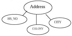
Address is composite attribute i. e. broken into HS_NO., COLONY & CITY attributes.
6. DERIVED ATTRIBUTE: A derived attribute’s value is derived from another attribute.
EXAMPLE: STUDENT (RNO, NAME, CLASS, ADDRESS)
AGE = CURRENT_DATE - DATE_OF_BIRTH
Here AGE is derived attribute because its value depends on CURRENT_DATE and DATE_OF_BIRTH.
RELATIONSHIP
Association among several entities. A relation is represented by a diamond symbol. Each relatin can have a name and properties also.
EXAMPLE: TEACHER TEACHES STUDENTS.
TYPES OF RELATIONSHIP: -
1. ONE-TO-ONE/ 1:1 / | |
2. ONE-TO-MANY OR MANY-TO-ONE/ 1:M /
3. MANY-TO-MANY/M: M
ONE-TO-ONE: For each instance of one entity there exist only one instance of another entity.
EXAMPLE: One person ran married withon1v one person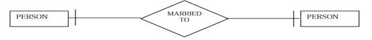
ONE-TO-MANY: For each instance of an entity there may be exist more than one instances of another entity.
EXAMPLE: One country can have more that one states.
MANY-TO-MANY: For each instance of an entity there may be exist more than one instances of entity b and vice versa also possible.
EXAMPLE: One EMPLOYEE can be assigned to more than one project & One project can be handled by more than one EMPLOYEES.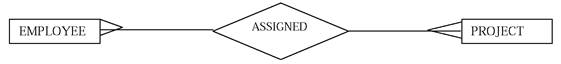
DEGREE OF RELATIONSHIP
1. UNARY: Number of entity is 1 involved in a single relation.
2. BINARY: Number of entities 2 involve in a single relation.
3. TERNARY: Number of entities 3 involve in a single relation.
SUPERTYPE & SUBTYPE
An entity that can be classified into more than one entities (subtypes) is called supertype.
EXAMPLE: SUPERTYPE: PATIENT(PNAME, ADD)
SUBTYPE: INPATIENT (WARD_NO, BED_NO.) OUTPATIENT (NEXT_APPPINTMENT)
CARDINALITY
Participation or involvement of entity instances in a relation.
TYPES OF CARDINALITY
1. OPTIONAL (MINIMUM NO. OF INSTANCES CAN BE ZERO)
2. MENDATORY (MINIMUM NO. OF INSTANCES AT LEAST ONE)
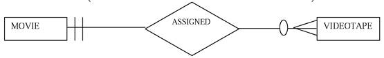
In a video shop if videotape available than its is of some movie means for existence of videotape, the existence of movie is compulsory but for existence of movie the existence of videotape is not compulsory. Participation of movie is mandatory but participation of videotape is optional.
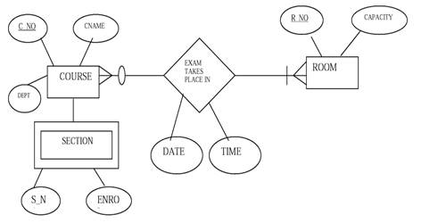
Example of ER-Diagram
Consider a university database for scheduling for classrooms for final exams. There are exams taking place for various courses. Each course has a unique name, department and a course number. For each course there may be many sections. Sections have a section_number and enrollment. There are multiple rooms available in various buildings. Each room is identified room_number, seating capacity and building_number and is reserved for one or more courses exam. For each exam date and time are stored.
Steps of developing an ER diagram:
1. List all entities, attributes and relationships.
2. Find types of relationship and cardinality between entities.
3. Draw ER diagram according to given standard notations.